
For campuses, residential communities, factory areas, and public parking areas. Through the SG-I-B smart IoT gateway and the Tongwei Smart AIoT operations platform, view distribution circuits, environment, and charging-equipment status in one place, connect authorized fire and security events, and support graded notification, video verification, and work-order tracking.
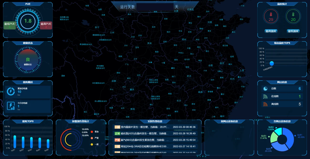
Tongwei Smart software screen · multi-site power and environment overview example
Where it applies
Property management and campus operations can locate shelter areas, equipment, and circuits in the same site view. Site points, interfaces, and fire configuration are set from vehicle type, space conditions, and existing systems.
Concentrated e-bike charging shelters
For outdoor or semi-open shelters, connect the status of outlets, charging cabinets, or battery-swap cabinets, monitor branch power loss, temperature and humidity, and standing water, and bring together authorized fire events and video information.
Electric-vehicle charging spaces and shelters
Connect online, fault, and operating status of AC chargers or DC chargers, monitor incomer and branch load, view emergency-stop or cutoff feedback, and add branch energy statistics where needed.
Central management of multiple shelters and sites
Use one coding scheme across campus, site, shelter area, circuit, and equipment. Equipment of different brands is connected by zone. Duty notification and response permissions are configured by site and shift.
For underground, semi-underground, enclosed, or in-building sites, the project’s specialist party determines the fire design and the interface scheme. The platform can connect to zones, points, faults, and interlock feedback that the fire alarm control panel or the original-manufacturer gateway is authorized to output.
System architecture and data flow
The site gateway collects meters, sensors, and status signals. Existing fire, charging-operations, and video-security systems provide events or status through their own authorized interfaces. The Tongwei Smart platform handles unified modeling and operations.
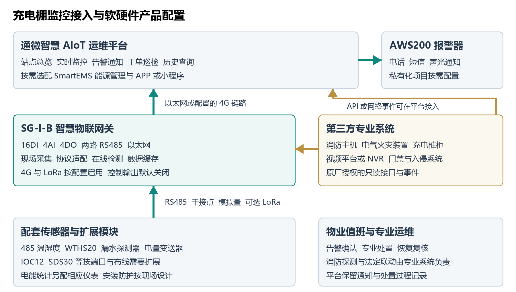
Charging-shelter monitoring connection architecture and hardware and software configuration
Field equipment to the edge gateway
Temperature and humidity, power meters, and expansion modules connect over RS485. Water leak, door contact, trip readback, and authorized fire summary signals can connect to DI through isolated dry contacts.
Third-party systems to the platform
The fire original-manufacturer gateway, the charging operations platform, and the NVR or video management platform can provide network events, API, or MQTT under authorization. The platform or an adapter service handles protocol and field mapping.
Platform to duty and operations
The gateway reports over Ethernet or over 4G as configured. The platform associates measurement points with shelter area, equipment, and responsible group, and carries out alarm grading, notification, video association, and work-order flow.
Fire-system responsibility. Fire detection, alarm, suppression, and statutory interlocks are carried out by the specialist fire system. Tongwei Smart connects, read-only, to fire events and feedback through an interface authorized by the owner and accepted by the original manufacturer, for display, notification, and records.
Monitoring points and third-party interfaces
Check existing equipment and vendor interfaces first, then set measurement points, collection intervals, alarm thresholds, and responsible persons. The table below can be the starting point for a single-shelter survey and for developing the point list.
| Monitored object | Data or events that can be connected | Interface and field checks |
|---|---|---|
| Fire alarm control panel | Fire alarm, fault, disable or isolate, restore or reset, and interlock feedback. A detailed event can include zone, address, and source time. | Original-manufacturer authorized protocol, original-manufacturer gateway, or isolated dry contact. A summary contact can provide only the agreed status. Address-level events require the protocol interface to be opened. |
| Electrical fire-monitoring device, in-cabinet detection | Device alarm, fault, and communication status, plus residual current, temperature, or in-cabinet suppression-action feedback where configured and opened. | Read from the specialist device or from an interface authorized by the charger or cabinet manufacturer. Alarm decisions and protective actions remain with the source system. |
| Distribution incomer and branches | Voltage, current, power, power factor, frequency, energy, open and close, trip, and power loss. Harmonics and similar items are selected by meter field. | A multifunction power meter connects over Modbus. Branch status can be collected through isolated digital inputs. Electrical specialists check the CT ratio, circuit labels, and readings. |
| Charging piles and charging cabinets | Online, idle, charging, port status, fault code, charging power or energy, and emergency-stop and cutoff readback. | Manufacturer-authorized API, protocol, or dry contact. Confirm against the equipment model, firmware, and opened point list. Protection, control, and operations billing remain with the original system. |
| Temperature and humidity, cabinet temperature, and standing water | Temperature and humidity inside the shelter or cabinet, temperature limit exceedance, probe fault, and standing water in low spots or at the cabinet base. | RS485 temperature and humidity, or a matching LoRa probe. A leak module can connect to DI. Set probe location and alarm delay against rain, wash water, and drainage conditions. |
| Video surveillance | Camera or recorder online, channel and recording status, authorized video link, and video-analytics events. | Connect to the existing NVR/VMS. Recording storage stays on the original video system. Smoke and flame recognition results are video-analysis events for the person on duty to check. |
| Access control and intrusion | Door-contact open and close, door held open, unauthorized door opening, intrusion-zone alarm, and controller offline. | A door contact can connect to DI. Access and zone events connect through an interface authorized by the controller or platform. |
| Communication and backup power | Online status of the gateway, sensors, and third-party interfaces, last update time, link and cache status, and optional UPS or DC power-supply status. | Gateway diagnostics and the vendor protocol. Offline is explicitly marked as a data interruption, and local cache and recovery backfill are checked per configuration. |
Dry contacts
Check normally open or normally closed, normal and power-loss states, isolation method, and open-circuit behavior, and compare equipment and platform status channel by channel.
RS485 / Modbus
Confirm device address, baud rate, parity, register address, data type, byte order, multiplier, and polling interval.
Network protocols and API
Confirm version, authentication, event subscription, timestamps, fields, and network access scope, and schedule tests for interface failure and recovery.
Site gateway and associated products
Use SG-I-B as the on-site collection core. Set the number of gateways and expansion modules from point count, installation distance, power supply, and communication conditions.

SG-I-B smart IoT gateway. Standard 1U, 432 × 200 × 44 mm. Outdoor deployment uses a protective enclosure selected for site conditions.
Port allocation example for one connection zone
The example uses 8 DI channels, with 8 channels reserved. Actual ports are assigned from the confirmed site point list.
| Interface resource | Allocation example | Configuration points |
|---|---|---|
| DI 1–8 | 1 water-leak channel, 1 cabinet-door contact, 2 trip and closed-position readback channels, 1 power-loss channel, 2 authorized fire-alarm and fault summary channels, and 1 charging-equipment fault summary. | Check each channel against the source equipment output, and make clear what a summary point means and how it behaves on power loss. |
| RS485 bus 1 | Temperature and humidity transmitters and collection modules whose communication parameters are compatible. | Use the same communication parameters and a unique device address on the bus, and check polling and communication quality on site. |
| RS485 bus 2 | Power transducers, energy meters, or charging equipment that has a matching driver. | Confirm firmware and drivers. Group equipment whose communication parameters differ by interface conditions, or add a separate adapter. |
| AI, DO | Connect AI, where needed, to analog signals whose range matches. DO can be configured per project for ordinary auxiliary audible and visual output. | When AI is reused as DI, count the resources together. DO is off by default. Fire actions and charging main-circuit protection are carried out by the specialist systems. |
| Ethernet, optional wireless | Ethernet uplink, with a 4G link and LoRa sensors configured where needed. | Check the module, antenna, SIM card, and sensor version against the order, and verify coverage on site. |
Sensors, expansion modules, and notification devices
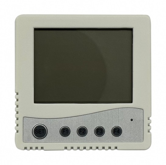
485 temperature and humidity transmitter. Local display, RS485 / Modbus, DC 9–28 V.
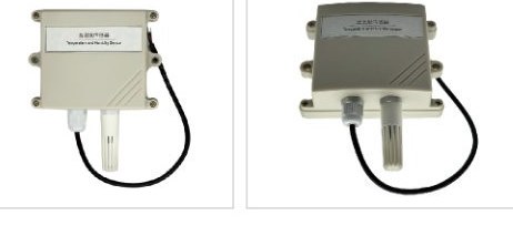
WTHS20. Battery powered, reports over LoRa, for points where cabling is difficult.
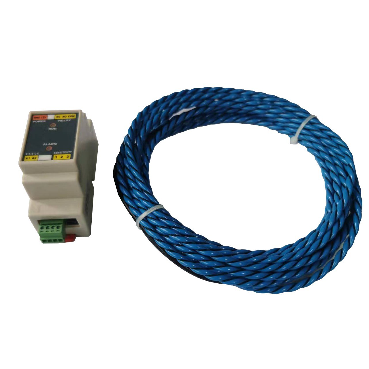
Water-leak detector and sensing rope. Relay output to DI. An RS485 version is also available.
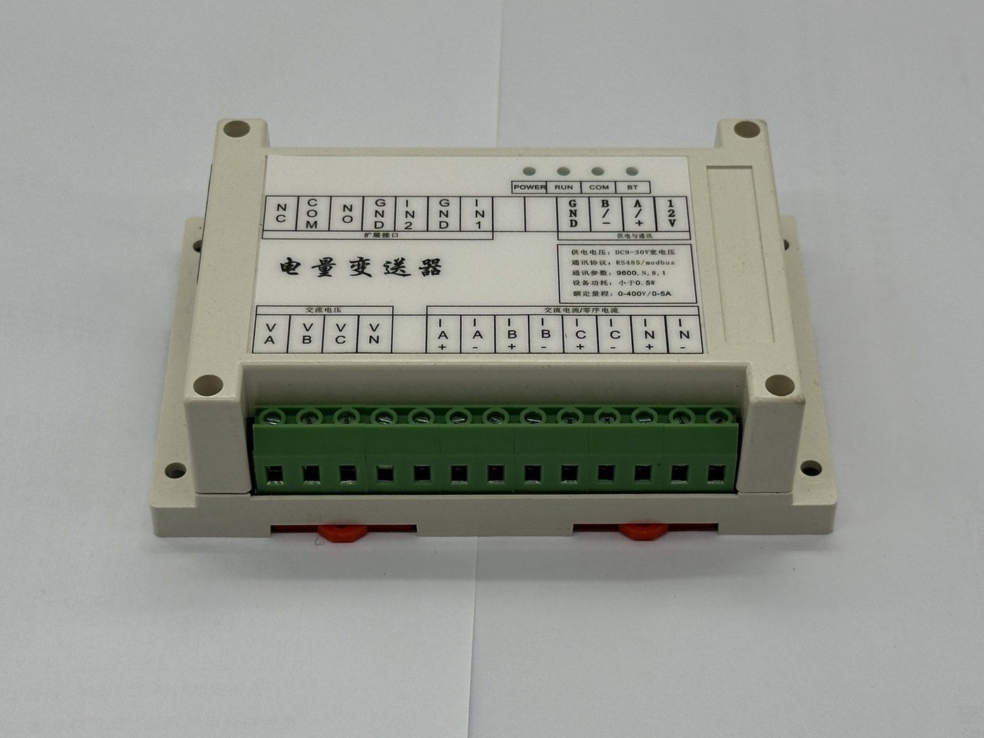
Power transducer. Voltage and current over Modbus. Power, energy, and time-of-use statistics require a separate matching meter.
IOC12. 12 inputs and 12 outputs, RS485 / Modbus expansion.
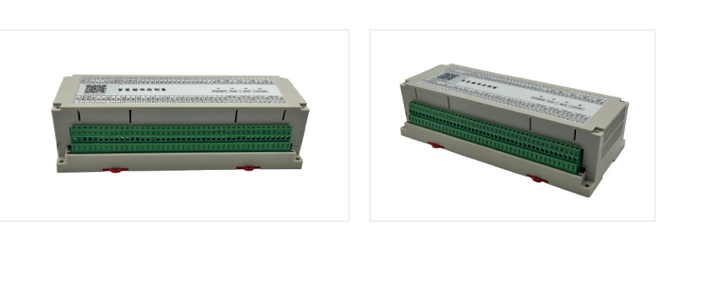
SDS30. 32 inputs and 9 outputs, dual-power hot standby, suited to centralized expansion.
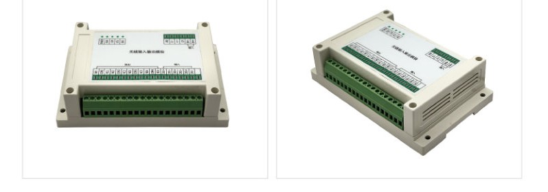
IOC08. 8 relay outputs, for ordinary auxiliary signals that have been confirmed.
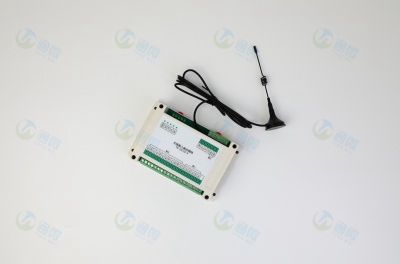
IOC44. 4 inputs and 4 outputs, for non-safety-critical points where cabling is limited.
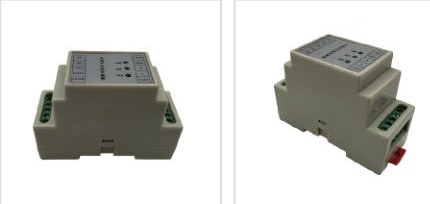
ETS10. 2 inputs and 1 output, linking LoRa and RS485 collection.
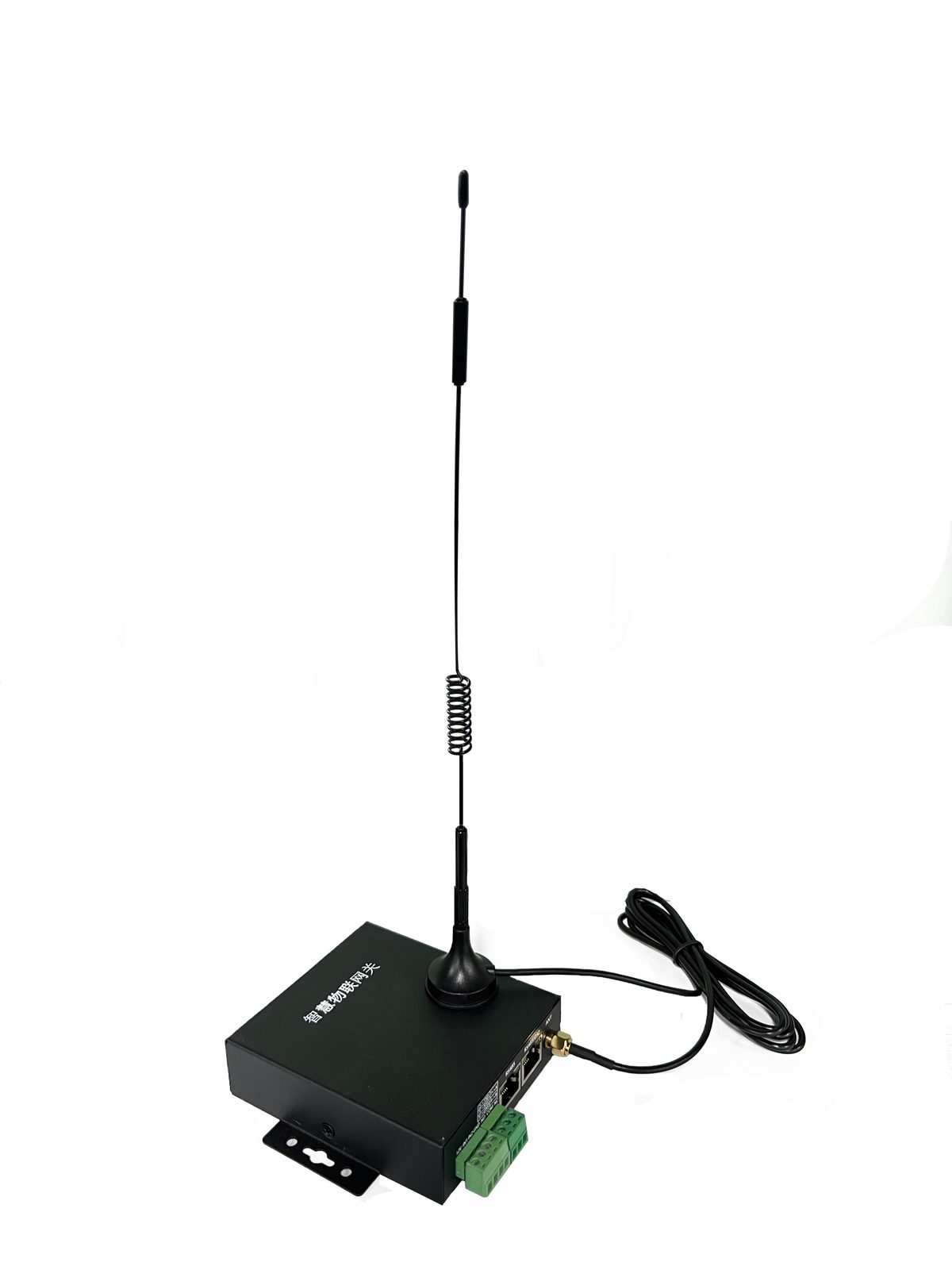
AWS200. Optional for private-deployment projects. Can be configured for phone, SMS, or ordinary on-site audible and visual notification.
Software platform and screen examples
The Tongwei Smart AIoT operations platform provides a multi-site ledger, real-time monitoring, historical data, alarms, and work orders, and supports SaaS or private deployment for the project. SmartEMS energy management, mobile inspection, configuration dashboards, and third-party interface services are selected per project.
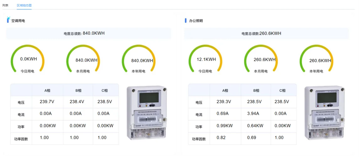
Real-time circuit power. View branch load and electrical quantities by meter fields.
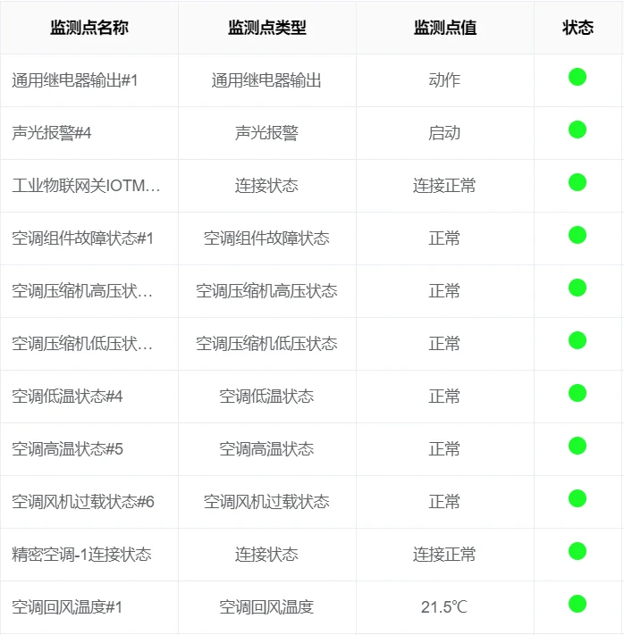
Real-time points and equipment status. Check by site and equipment category, and locate abnormal points.
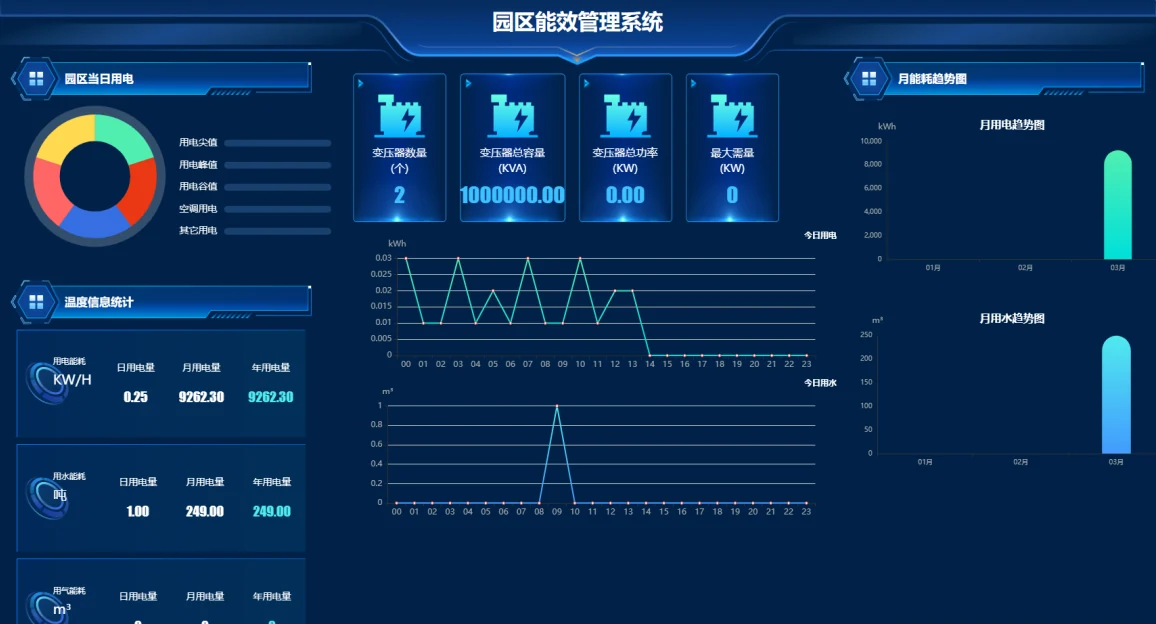
Campus energy-efficiency analysis. Use SmartEMS to view sub-metered energy, peak, flat, and valley, and period trends.
The screens are taken from Tongwei Smart’s existing power and environment software and energy-efficiency software. An actual project configures base maps, measurement points, and permissions by shelter area, distribution circuit, equipment, and fire zone. Mobile inspection can use an app or a mini program, per project, to accept work, take photos, and submit results.
Alarm grading and response process
The platform can be configured with four levels of operations events: urgent, important, general, and advisory. For example, a fire alarm from the fire alarm control panel is notified under the emergency plan, power loss on a critical circuit is assigned first to the person on duty and the equipment owner, and an ordinary environmental limit exceedance goes to daily operations. Recipients, time windows, and escalation rules for each level are confirmed per project.
| Typical event | Platform handling | On-site responsible party |
|---|---|---|
| Fire alarm from the fire alarm control panel | Keep the original event and zone, notify the designated people under the emergency plan, and provide video clues the viewer is authorized to open. Platform acknowledgement is independent of silence and reset on the source system. | Fire control room duty staff, property management, and the fire specialist respond under the emergency plan. |
| Fire fault, interface offline | Map the source-system status to an equipment fault or an interface interruption, show the last update time, and notify the responsible person. | Fire maintenance, the system vendor, or network maintenance staff investigate. |
| Branch trip, charger or cabinet fault | Associate the circuit, source status, alarm code, and electrical quantities, and notify at the level agreed for the project. Repeated offline reminders caused by the same fault can be merged. | Electrical specialists, or the charging-equipment operator and maintenance party, verify and handle it. |
| Water immersion, temperature and humidity limit exceedance, door contact, or video event | Notify operations or security by site, time window, and event level, and associate video and real-time points to help verification. | Duty staff verify on site and handle it under the operations or security process. |
| Gateway or network offline | Mark the data interruption and the last update time, and notify maintenance staff. After the link recovers, check cache, backfill, and duplicate records per configuration. | Network and operations staff investigate the link, the gateway, or the third-party interface. |
- Receive and notify. Store the original event, zone, and source time, and notify the responsible person by shift and level.
- Accept and verify. The person on duty confirms acceptance and checks against real-time data, authorized video, and site conditions.
- Specialist response. Hand the event to the corresponding responsible party under the project plan, and record the time, result, and site photos.
- Review and close. Confirm that the source signal has recovered, then close the work order after review. Unconfirmed, overdue, or failed notifications escalate under the project rules.
Project implementation and acceptance
A campus that already has systems can first pick one representative charging shelter, verify equipment interfaces, point mapping, notification delivery, and work-order close-out, then copy that to other shelter areas.
- Site survey. Confirm the site type, equipment brands and models, power-distribution and network conditions, original-system interfaces, and each party’s responsibilities.
- Design development. Produce the topology, point list, alarm matrix, interface confirmation sheet, port budget, and supply list.
- Equipment supply and installation. Tongwei configures the gateway and platform. The site contractor completes installation, cabling, and labeling to the specialist drawings.
- Subsystem joint commissioning. Check power and environment points, charger and cabinet status, authorized fire events, security video, and notification channels in turn.
- Acceptance and training. Deliver the configuration backup, point list, interface mapping, joint-commissioning record, operating instructions, and issue list.
- Trial operation and tuning. Check alarm quality, notification delivery, communication availability, and work-order response, and tune thresholds, time windows, and the notification strategy.
How to accept on site
| Acceptance item | Check method and delivery record |
|---|---|
| Collection and ledger | Compare on-site displays with sampled platform points, and check equipment IDs, points, units and multipliers, status, update time, and communication quality. |
| Fire and video | Tests are organized or approved by the fire specialist. Verify mapping of fire alarm, fault, zone, and restore. Check associated video channels, viewing permissions, and platform logs. |
| Notification and work orders | Simulate typical events and verify shift and responsible person, delivery receipt, escalation when unconfirmed, failure prompt, response record, and close on recovery. |
| Link loss and recovery | Per the project agreement, verify the offline mark, last update time, cache, backfill, and duplicate records when the platform link is interrupted. |
| Deployment and permissions | Check site hardware and optional modules, account permissions, interface access, logs, backup, and data-retention configuration. |
Choose the deployment form by site scale
Basic connection
For a single shelter or a small number of shelters. Collect basic power and environment data and electricity data, connect authorized events from existing systems, and configure the ledger, alarms, and work orders.
Central operations for multiple shelters
Add charger and cabinet protocols, video association, access-control events, multi-site permissions, reports, and mobile inspection. Energy metering can be added where needed.
Multi-site private deployment
Deploy locally to the owner’s network and data requirements, and configure zoned access, time synchronization, backup and recovery, and third-party system interfaces. AWS200 can be selected where needed.
Materials needed before the project starts
Tongwei Smart supplies power and environment equipment, edge gateways, the operations platform, and the agreed interface adaptation and joint commissioning. Configuration quantities and delivery scope are set from site materials and interface verification.
- Site and power distribution. Shelter-area plans, shelter count and number of charging positions, power-distribution diagrams, and circuit and network lists.
- Existing systems. Brand and model, interface manuals, point lists, and authorization conditions for the fire alarm control panel, charging piles and cabinets, video, and access control.
- Duty and deployment. Fire zones, responsible groups, duty arrangements, notification methods, platform deployment location, and data-retention requirements.